The problems of testing 5G: Part 2
This article is from the CW Journal archive.
In the first part of this article, I outlined the context for 5G and some key attributes of the New Radio (NR) air interface being developed by the 3rd Generation Partnership Project (3GPP).
Last month saw a major milestone with 3GPP approving the first version of the NR specifications. These are for the non-standalone (NSA) version of 5G which uses an LTE anchor carrier augmented by an NR carrier. The standalone (SA) specifications, or pure NR, are targeted for June 2018. But before we get too excited by the phenomenal progress being made by 3GPP in attempting to define 5G in half the time it took to define 3G and 4G, it is worth taking a closer look at what has just been published.
The Release-15 NR specifications comprise 82 technical reports and specifications covering everything from the physical layer through to network aspects. They can be found at www.portal.3gpp.org by entering '38' into the search field of the specifications tab. The specifications can be split into core requirements for what needs to be done (such as, basic RF aspects like power accuracy, signal quality, channel coding, signalling procedures) and performance requirements for the softer aspects of how well something needs to be done (for example, throughput performance in non-ideal conditions or time taken to search for a new cell).
Testing processes we have been using since the days of Marconi are finished
When the first LTE specifications were published in December 2008, they were quite comprehensive. However, the equivalent NR specifications in December 2017 only cover core specifications, with the performance requirements not being due until December 2018. In practical terms, this means we have a solid basis for NR at the physical and signalling layers, but only basic RF requirements and no radio performance requirements for another year. For that reason, the page count of the new NR radio specifications is only about a fifth of what LTE had first published.
In anticipation of the seismic changes in methods caused by the move to mmWave frequencies (> 24GHz, known now as Frequency range 2 or FR2), the test industry has been developing proposals throughout 2017 under a 3GPP 'testability' study item. The major driver here is that at FR2, the cables we have been using to connect test systems to the device under test (DUT) will not exist, and all conformance, and much lab testing will need to be done over the air (OTA).
Another thing we have learned from 3G and 4G is that it is not just developing OTA test methods that has been challenging but also the specification of UE performance requirements. This fact became brutally evident in Dec 2017 when 3GPP decided, after five years of effort, to abandon attempts to agree SISO TRP requirements for LTE smartphones.
The problem was that too much time had elapsed between the 2008 Release 8 specifications and the effort to define performance requirements.
During that time, only the conducted output power was specified, and the radiated power – the bit that makes the system work – was unspecified. Measurement of more than 1,000 different device designs showed a spread in performance of around 15dB meaning the worst devices are less than one per cent efficient.
With such a wide variation in measured data, and the additional complications caused by carrier aggregation, no agreement could be reached on TRP for LTE.
The worst of today's smartphones are wasting 99 per cent pf power through the antenna
Putting this in a different way, the conducted power is like the torque reaching the axle of a car, and the radiated or useful power is the force reaching the road. The worst of today's smartphones are wasting 99 per cent of that energy through the antenna and that really matters when it comes to user experience in cell edge and indoor environments.
For MIMO OTA the situation was slightly better in that UE requirements were finally agreed, but for reasons that I don't have space to explain, the requirements provide no real insight into the gain MIMO might be bringing to realistic networks.
Anecdotally, I've hear that 2x2 MIMO provides maybe 20 per cent gain in an average network, but we have no testable requirements today that demonstrate that. Shakespeare must have had a premonition about the potential of MIMO when he wrote Much Ado About Nothing.
Looking ahead to 5G NR, many of the key technical benefits at both FR1 and FR2 are tied to further exploitation of the spatial domain through massive MIMO at FR1 and beamsteering at FR2. As of today, time pressures within 3GPP mean that the development of testable spatial requirements for demod and RRM are being squeezed out of Release-15 to cope with the accelerated timescales. This is a big gamble for the industry since for 5G to deliver at the radio level will require network equipment to be developed that meets currently unwritten spatial OTA performance requirements.
We now know how the industry responded to not having SISO TRP requirements – many designed poor products and got away with it to our loss. This should be a clear warning for what could happen if NR is implemented before critical OTA requirements are specified.
I hope the insights you have picked up from these two articles on the challenges of testing 5G have been useful and that it will help steer the industry towards a successful specification and deployment of 5G in the near future.
With the inevitable increased time and costs of having to move to OTA testing, it is essential that we focus, and test what really matters. At FR1 the question being asked for the last 100 years was: "How good is my signal?" However, 5G NR brings a new paradigm which is: "Where is my signal?" since if it is pointing in the wrong direction its quality is no longer relevant. We in the test industry are working to help you find your 5G signal!
There are two drivers for this transition from cabled to OTA test. The first is that due to high transmission losses, both base stations and mobile devices will need to employ high gain directional antenna systems, and today's method of connecting cables to temporary antenna connectors doesn't scale due to cost, space and accuracy.
The second reason is that in the world of mmWaves, signals only take on meaning when observed as wave fields at some distance from the antenna arrays. Even if each antenna element could be probed, the extrapolation of such measurements cannot accurately represent the actual signal in space. So, in an instant, the familiar world of cabled testing we have been using since the days of Marconi are over!
Now we do have some experience with OTA requirements and testing from 3G and 4G, but these were add-ons to the bulk of requirements and testing which relied on galvanic connections. For 5G at FR2, all testing needs to be OTA. This is a huge issue since we know OTA testing is less accurate and much more expensive, and on top we need to deal with the 3D spatial domain which makes OTA testing much slower.
Project managers know they would like to optimise for good, cheap and quick, but only two choices can be optimised at any one time and the third accepted. But when it comes to OTA testing, we will be faced with no choice but to accept poor, expensive and slow. This situation, caused by the physics of mmWaves, is what has been keeping the test industry awake at night.
We get some idea of the challenges when we compare the basic cabled RF tests below 6GHz (frequency range 1 – FR1) with the SISO (single antenna) OTA tests introduced in 3G. Cabled measurement uncertainty (MU) is much less than 1dB, and power measurements take only a few ms to complete - and the connectivity aspect of the test system is the cost of a cable.
Contrast this with measuring total radiated power (TRP), which is the aggregation of transmitted power measured over a sphere. To measure TRP requires a far field anechoic chamber (or reverb chamber) with a range length of around 3m, which has an accuracy of around ±2 dB. Test time per frequency band (of which there can be > 20 in a single UE these days) for bottom, middle and top channels takes around six minutes. This gap between cabled and OTA testability got worse with LTE (4G) when MIMO OTA was introduced. In MIMO OTA the test system must emulate a 2D spatial field with added channel propagation impairments to measure the achievable throughput of the DUT. A multi-probe MIMO anechoic chamber is much more expensive than a simple single probe SISO chamber, as well as needing channel emulators to drive each probe. The accuracy is not much worse at around ±2.5 dB but the current test metric takes up to two hours per DUT orientation.
So, if on the grounds of MU, speed and cost, today's cabled testing could be described as good, then FR1 OTA, relatively speaking looks more like bad. But then when we look at 5G OTA at mmWave frequencies the only word that fits is ugly!
For example, the new 3GPP NR specifications include a provisional figure for power measurement uncertainty of a whopping ± 6.7dB. The reasons are complex but with today's technology this is the industry consensus although we are working hard to reduce this. The costs for FR2 are also higher than FR1 and the need for time-consuming comprehensive 3D analysis is much greater than at FR1.
Tests for the UE and base station fall into three main groups:
- RF requirements in ideal radio environments
- Demodulation (demod) receiver requirements in impaired RF environments
- Radio resource management (RRM) requirements in 3D static and dynamic environments
The Direct far-field measurement method
At FR1, most NR tests will be carried out using existing conducted methods although there will be a need to evolve the existing UE MIMO OTA requirements developed for LTE to take account of the higher frequencies up to 6 GHz, and possibly higher order MIMO (up to 8x).
At FR2, all tests will be OTA, and since the test environment for each type of requirement are quite different, this will lead to three quite different classes of test system.
|
GET INVOLVED WITH THE CW JOURNAL & OTHER CW ACTIVITIES |
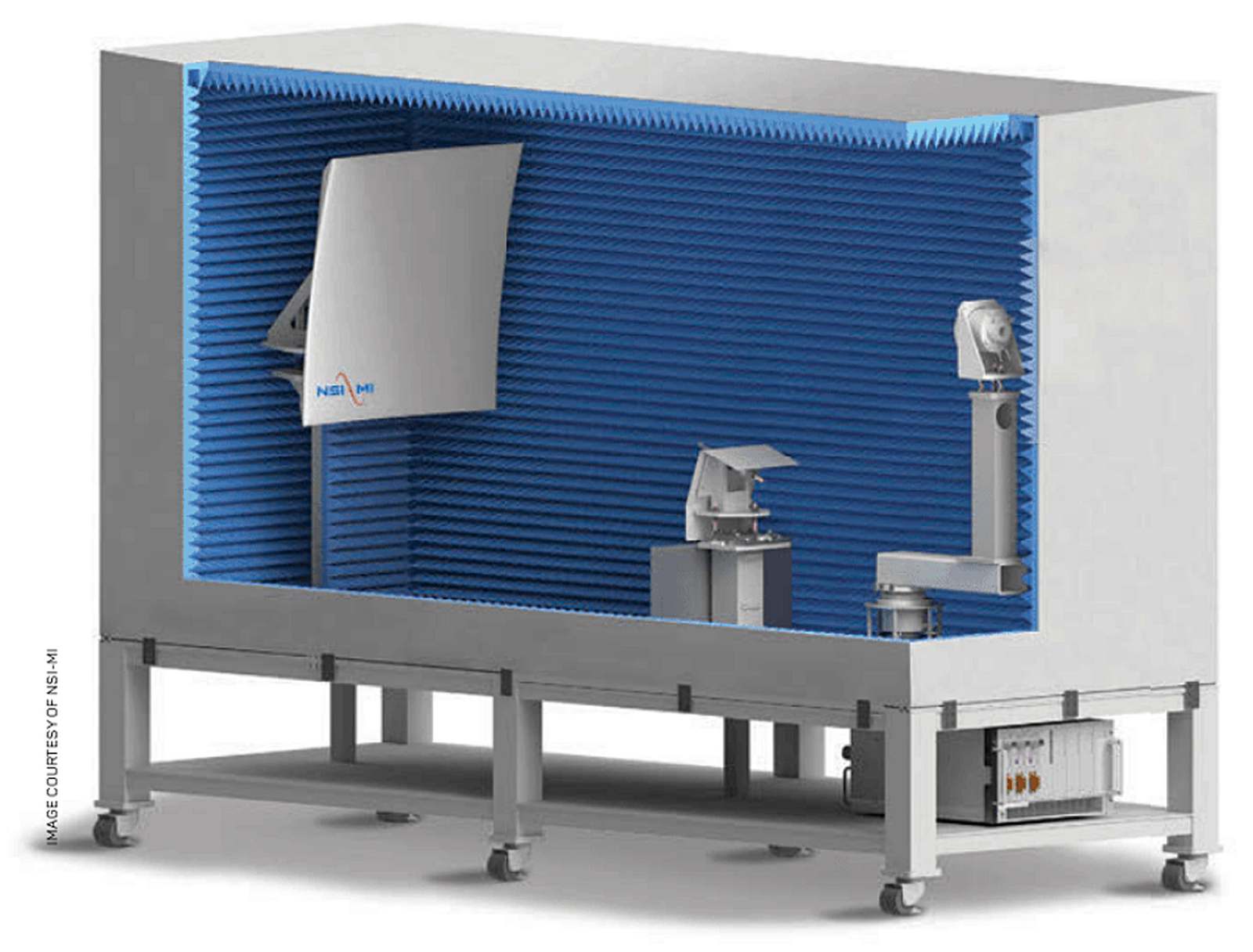
The simplest test method is for the RF requirements which cover transmitter and receiver characteristics in ideal line of sight conditions. The baseline UE RF test method comprises a link probe antenna for setting up a call to which the UE forms its beam, and a second probe which can independently move over the sphere to measure or stimulate off axis performance. Off-axis probing is required to measure TRP and some other tests. The radius of the baseline system is based on the far field distance d computed from the Fraunhofer equation 2D2/λ where D is the aperture of the radiating elements of the UE.
The UBF clearly has a big simplifying impact on the RF baseline test method however the range length is still large and means that it is not possible to measure accurately unless assumptions about the antenna design being smaller than the device size allow the far field distance to be reduced.
Alternate test methods are also being pursued by 3GPP and the most promising is the compact antenna test range (CATR) which incorporates a parabolic reflector to transform the diverging test signal into a collimated beam, emulating ideal far field plane wave conditions. The advantage this transformation provides is that the focal length of the probe to the reflector is typically 0.7m for a quiet zone wide enough to cover typical handheld devices and base station antennas.
CATR receiver test showing collimation of the test signal by the reflector
The principle of a CATR is clear for receiver testing but the system is reciprocal and works for Tx testing since only the plane waves hitting the reflector from the UE are focused back to the probe antenna.
The base station FR2 RF test methods will be based on the methods developed for active antenna system (AAS) base stations at FR1 which are the far-field anechoic chamber, CATR, and near-field probing which involves a Fourier transform of close-in measurements to predict far field fields.
At FR1 there are two methods approved in 3GPP TR 37.977 for testing the MIMO OTA demodulation performance of UE receivers in spatial fields. The first is the multi-probe anechoic chamber (MPAC) which uses a ring of probes to emulate a 2D spatial field, each probe being driven by a channel emulator. The second method is called the radiated two-stage method (RTS) and uses a completely different approach to achieve the same result as MPAC.
In the first stage, the UE receiver antenna pattern is measured in a SISO chamber with the help of an antenna test function in the UE. In the second stage, the measured pattern is convolved with the desired spatial channel to create the signals that would have been seen by the UE receiver had the device been placed in the desired spatial field. These signals are then radiated to the UE at one angle through its antenna but with the antenna gain at that angle de-embedded.
That's a lot to take in at once, but an ideal RTS system is mathematically equivalent to an ideal MPAC system.
CATR Transmitter showing how only the collimated signal from the DUT converges on the measurement probe
Extending the MPAC method from FR1 to FR2 is unfortunately not possible. The reason is that the size of the test zone, being the volume within the anechoic chamber where the correlation of the MIMO signals is controlled, is a function of the angular spacing of the probes. In a typical 8x2 cross-polarized system, the probe spacing of 45 degrees leads to a usable test zone of 0.85 λ, which is about 10 cm at 2.6 GHz – large enough for the spacing of the antennas on a typical smartphone.
Doubling the number of probes gives a test zone of around 2λ or 23cm. But at 39GHz, a 16x2 MPAC system would have a test zone of only 1.5cm. Adding sufficient probes to test a 15cm smartphone would be prohibitively expensive as they would need to be hundreds of them covering a full 3D sphere. A simplified sectored MPAC (SS-MPAC) system is being studied at 3GPP which may have some applicability. This emulates only part of the sphere using closely-spaced probes which are sparsely fed by only a few channel emulators.
A simpler approach is the extension of the RTS method to FR2 since it relies on the parameters of a SISO chamber. This means that whatever method (far field or CATR) works for the RF tests, could be extended to implement an RTS approach for throughput testing in spatial fields with the antenna pattern included.
The one caveat with the RTS method is that it does not apply if the DUT antenna might change its pattern during the test. Fortunately, with the specification of the new UE beamlock function (something base station testing already relies on), the RTS method will work for arbitrary 3D spatial fields where the signal direction is static.
More complex dynamic spatial fields are out of the current demodulation test scope. It is also possible using the RTS method to ignore the DUT antenna pattern and emulate what a cabled connection without antenna would look like. This has benefits for assessing the RF and baseband performance of the DUT independent of its antenna thus looking like the legacy cabled test approach.
Simplified sectorized multi-probe anechoic chamber (SS-MPAC)
The RRM test environment is the most complex to emulate since most tests require the generation of at least two signals from different directions. Examples of RRM test cases might be the measurement and handover of a UE from one cell to another. At FR1 this would be done with cabled test signals with no spatial content, but at FR2, the signals exist only in space with a narrow angular spread of perhaps 10 degrees.
It is easy to see how to set up a simple RRM test system with two fixed directions, but to be effective, the test system needs to be able to alter and randomise the angles of arrival to avoid the DUT learning the test sequence. More sophisticated test sequences would involve dynamic signals in space to emulate the UE travelling through the environment. Emulating this would require dynamically moving signals in the anechoic chamber which creates considerable practical challenges compared to a simple switched system with fixed angles.
The RRM test case which may represent the most challenging environment to emulate is the one required to test initial call setup, or acquisition of a new FR2 cell. Prior to establishing an FR2 link, the UE needs to first find the cell in space. The beam widths of typical base stations are in the order of 10 to 15 degrees, and the UE also has some antenna steering capability of its own as well as a random orientation towards the network due to being handheld.
Simplified RRM test system with fixed probes
The procedure to enable the UE to find the base station involves the base station transmitting synchronization signals in up to 64 different directions during a 5ms burst repeated every 20ms. During each cycle, the UE would select its own antenna direction and determine based on time of arrival, which base station beam identifier gave the best (if any) signal. The UE would then transmit back to the base station using that direction.
Emulating such a dynamic environment is not possible using the RTS method as the antennas are not static. This is where a method like the SS-MPAC would come into its own since by using signal switching, it could emulate the necessary signal directions to match the base station dynamic transmissions.
Moray Rumney received a BSc in EE from Heriot-Watt University in 1984. He joined Hewlett-Packard that year and remained with the company through the transition to Agilent Technologies in 1999 and Keysight Technologies in 2015. Moray joined ETSI in 1991 and 3GPP in 1999 where he participated in the development of cellular communications standards and conformance test methods. His recent work has focused on radiated test methods for mobile phones. He was editor and major contributor to Agilent’s book “LTE and the Evolution to 4G Wireless”. From 2018 to 2021 Moray represented Keysight at 3GPP RAN plenary who oversee the development of the 5G radio standards. His recent interests include expert witness work, engineering consulting services, and the safety debate around cellular technology including the evolution of test methods to validate that base stations and mobile phones comply with safety regulations.